❓ What is neutral axis?
Neutral axis is an imaginary line in a reinforced concrete section where longitudinal strain is zero. It separates the compression and tension zones, and its position depends on loading, material properties, and section geometry.
Common symbol in eurocode:
x🧐 What is strain?
To understand better about neutral axis, we first need to understand strain.
Strain describes how much a material stretches or squishes relative to its original length — it is a ratio, not a force.
For example, if a 1000 mm bar deforms by 1 mm, its strain is 0.001. Explore the interactive graphic below to understand this concept.
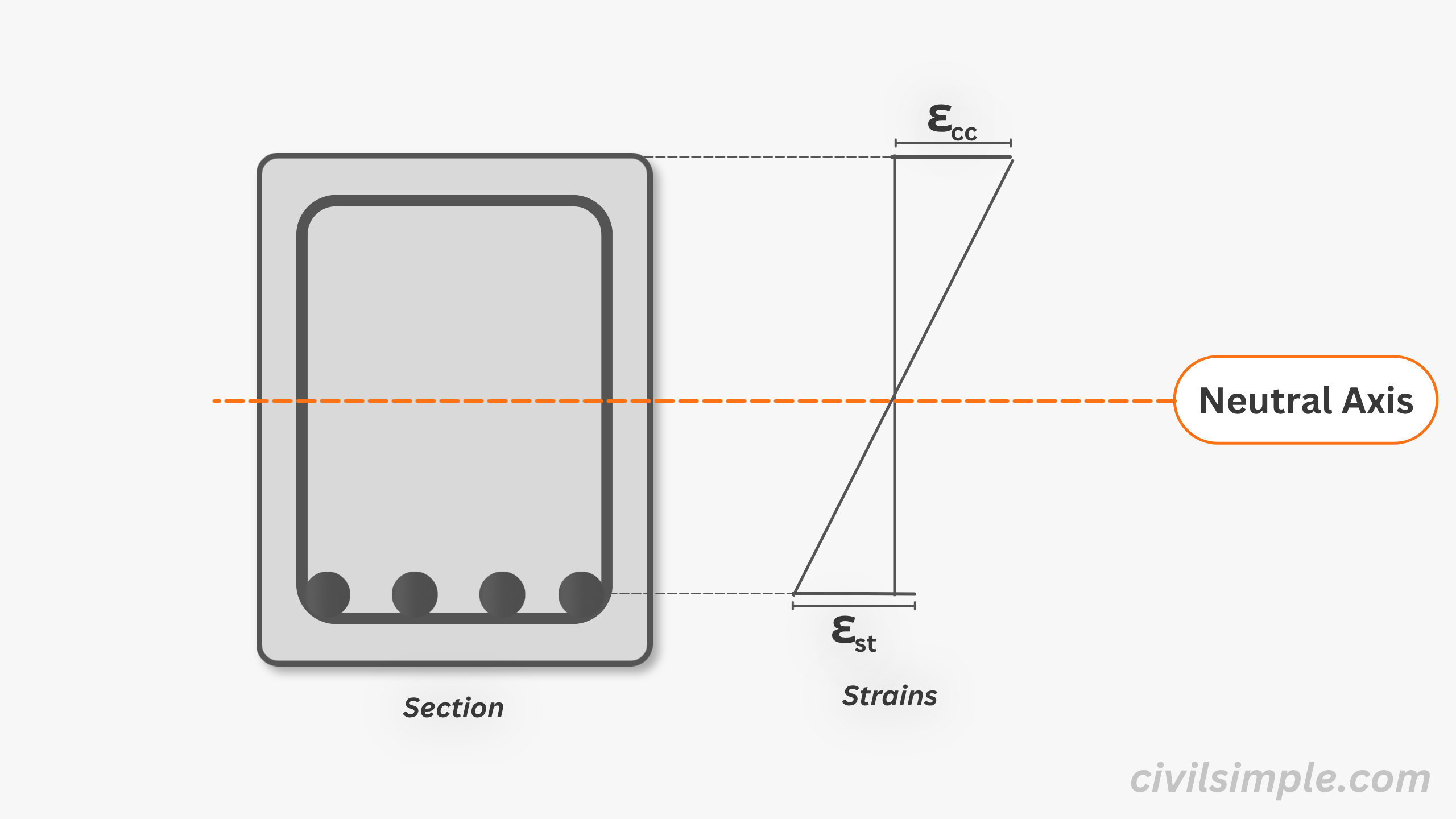
🤔 How the strain plane looks?
To develop the moment capacity of a section, a reinforced concrete section is divided into a compression zone and a tension zone.
- In the compression zone, the material is squished — this is called compressive strain.
- In the tension zone, the material is stretched — this is called tensile strain.
The strain varies along the section — the further a point is from the neutral axis (toward the outer edge), the greater the strain. At the neutral axis itself, strain is zero.
Plane section remains plane - after straining, section will be linear distribution of strains.
Details please refer to bending thoery and how the corresponding calculation satisfied that.
🔁 Will neutral axis change? How?
The neutral axis is not fixed — it may shift as the moment change. If tension reinforcement reached plastic zone first, the NA will move like below figure.
Normally, in most of the RC section moment design, we will focusing on the Ultimate Limit State (ULS) and calculate the corresponding neutral axis, xu. However, please notice that neutral axis actually could be changed with design action(loading).
With the assumption of concrete not carrying tension, the behaviour of neutral axis can be described in three stages:
Stage 1 - Elastic behaviour of both materials:
Neutral axis remain constant both concrete in compression and steel in tension behave elastically. Stress is proportional to strain in both materials.
Stage 2 - Plastic behaviour (one material yields first):
As loading increases:
(i) Tension reinforcement reach plastic behaviour first (Steel yields first) :
Neutral axis decrease when moment increase, as strain of steel increase but stress remaining constant.
(ii) - Concrete reach plastic behaviour first while reinforcement still in elastic:
Neutral axis increase when moment increase, the compression stress change from prue triangle to trapezoid.
Stage 3 - both side reach plastic behaviour together:
Same as Stage 2(i), after tension reinforcement getting plastic(yield), neutral axis decrease when moment increase until it reach xu
What if concrete reach crash limit while tension still not reach plastic phrase
-
If the concrete reaches its ultimate compressive strain before the tension reinforcement yields, the section fails in a brittle manner due to concrete crushing while the steel remains in the elastic range. (See below left image)
-
This is an undesirable failure mode in reinforced concrete design. For this reason, Eurocode 2 limits the neutral axis depth ratio x/d to ensure a ductile failure mechanism, where the tension reinforcement yields before the concrete reaches its crushing strain.
-
Ductile behaviour shows warning through steel yielding and deformation before collapse (See below right image), while compression-controlled failure is sudden and brittle.
Concrete Crush First(over-reinforced failure)
Tension Reinforcement Yield First
↔️ Upper and lower boundary of neutral axis in RC design
To fullfill the assumptions, especially achieve the ductility of RC section. During design of the section, we need to ensure it fullfill:
In short,
[2] min. compression stripe
Below is a simple indicator about how neutral axis changes with x/d ratio.
Details of the underlying assumptions and the derivation of these values are explained in What is sssumptions of bending in beam/slab in reinforced concrete?.
📝 Summary & Key Takeaways
- The neutral axis is the line in a section where strain is zero — neither tension nor compression acts at this point.
- Strain varies linearly across the section — increasing the further you move from the neutral axis toward the outer edges.
- The assumption that plane sections remain plane is what gives us this linear strain distribution — and defines where the neutral axis sits.
- The neutral axis position depends on the loading stage — from near the centroid under low load, rising as cracks form, up to its limit at maximum load.
- To ensure ductile behaviour, the neutral axis depth is limited. In Eurocode 2, the ratio x/d is kept between 0.125 and 0.45 — ensuring tension steel yields before concrete crushes.
CivilSimple Team
The CivilSimple Team writes practical engineering guides for the profession and the curious. All articles are reviewed for technical accuracy before publication.