❓ What is lever arm?
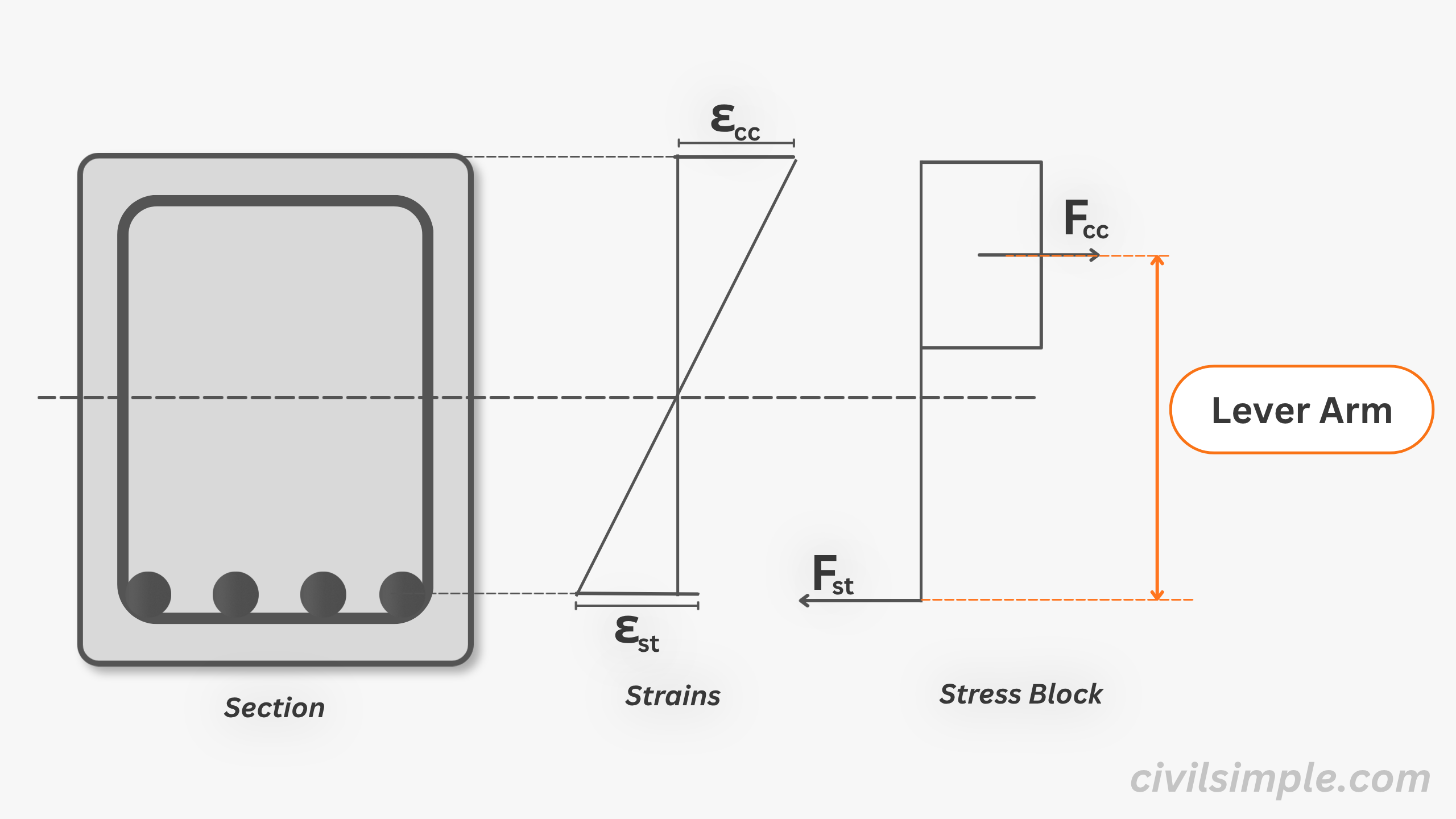
The lever arm is the distance between centre of the compression force and centre of the tension force acting on a section.
- centre of the compression force (Fcc)
carried by the concrete above the neutral axis
- centre of the tension force (Fst)
carried at the steel reinforcement below the neutral axis
The diagram below shows the idea of the lever arm in a reinforced concrete section.
Common symbol in eurocode:
z🤔 Why we need to know about lever arm?
Lever arm is the key parameter to compute the moment capacity of a reinforced concrete section.
The equation of moment capcity is:
🦾 Stress and Forces
To understand better about lever arm, we first need to understand stress and force.
The lever arm depends on the location of internal compression and tension resultants, which are obtained by converting strain → stress → force using the material behaviour of concrete and steel.
Therefore, before we can determine the lever arm, we must first understand how strain is converted into stress, and how stress is distributed to form internal forces.
📈 Know the strain-stress relationship for lever arm
In the article about neutral axis, we introduced how strain is distributed across a reinforced concrete section.
As the distance between center of coupling force indicates the lever arm, we need to locate the centres of these two forces.
1. Center of Tension Force (Reinforcement)
For reinforced concrete design, one key assumption is that all tensile force is carried by the reinforcement only, while concrete in tension is ignored (Concrete has very low tensile strength and cracks when subjected to tension).
Therefore, the centre of tensile force is simply the centroid of the tension reinforcement, located at the effective depth d.
1.1 Center of Tension Force Remain unchange
Try moving the strain in above diagram — the stress changes, but the force location stays fixed. And as strain increases in the steel, stress increases linearly in the elastic range until yielding. However, the location of the tensile resultant remains unchanged, even after yielding, because it is governed by the geometry of reinforcement.
2. Center of Compression Force (Concrete)
While center of tension force is pretty straight forward, it is not the same case in compression force.
Above diagrams show how concrete strain behave with stress. At the initate range, the strain is increase with stress before strain reach εc2. From εc2 to εcu2, even the strain increase, the stress is not increase.
As the parabolic curve Fig. 3.3, BSEN1992-1-1:2004 is hard to compute, especially when the day computer is not that common, to simplify, a conservative and simplified bi-linear distribution is introduced Fig. 3.4, BSEN1992-1-1:2004.
2.1 Center of Compression Force Move under different loading
Try moving the strain in above diagram — the stress changes, but the force location (centroid of stress) may changed based on the outermost strain change.
As all the concrete in compression side will provide compression force based on their corresponding strain, where compression force at top edge of section is offering higher stress while that close to neutral axis offered close to 0 stress.
Different Stages of compression zone
With considering the plastic zone behaviour, there will be 2 shapes of stress and 3 ways to illustrate:
1. All compression part lie in elastic zone (0 → εc2)
- Stress are in triangle shape
- Center of force located at
- Lever arm:
Stress and strain are proportional and parabola, meaning concrete behaves elastically — the section can recover if unloaded
2. Partially lies in elastic zone and partially lies in plastic zone (εc2 → εcu2)
- Stress are in tripizoid shape
- Center of force located at
- Lever arm:
Stress is constant at fcd regardless of increasing strain — concrete has yielded and deformation is no longer recoverable.
3. Majority lies in plasitc zone and only small portion in elastic zone (εc2 → εcu2)
- Stress are close to rectangle shape
- Force Stress are considered as 0.8x Cl. 3.1.7(3), BSEN1992-1-1
- Center of force located at
- Lever arm:
This is commonly happening at ULS stage.
🔢 Formula of lever arm at ULS
Figure3.5, BSEN1992-1-1:2004
Rather than a triangular stress block, most textbooks adopt a simplified rectangular stress block (0.8x) because the analysis of moment capacity is based on the Ultimate Limit State (ULS).
Therefore, to calculate the lever arm, we can use the below formulas:
At ULS, tension steel is assumed to have yielded.
Concrete compression is close to ultimate, allowing a simplified stress block for lever arm calculation.
🔄 Will lever arm change? How?
Similar to neutral axis, lever arm change when applied moment change.
Try to move below diagram, hope it can help to understand how section behave with loading under the EC2 assumption.
** Above diagram assume to demonstrate one of cases which tension reach plastic zone first.
After tension reinforcement reached yielded , the tensile force (Fst) is approximately constant. Therefore, since , increasing in moment will result in increase in lever arm.
↔️ Upper and lower boundary of lever arm in RC design
To fullfill the assumptions, especially achieve the ductility of RC section. During design of the section, we need to ensure it fullfill:
In short,
[2] min. compression stripe
Details about the assumptions and how the corresponding values come are covered in this article.
📝Summary & Key Takeaways
- The lever arm is the distance between the centre of the compression force and the centre of the tension force acting on a section.
- The moment capacity of a section is simply M = Force × lever arm — the larger the lever arm, the greater the moment capacity.
- The rectangular stress block simplifies the calculation, giving us z = d − 0.4x for concrete with fck < 50 MPa.
- The lever arm changes with load — similar to the neutral axis, it shifts as the section cracks and the stress distribution changes.
- In design, the lever arm ratio is bounded: 0.82 ≤ z/d ≤ 0.95 — ensuring ductile behaviour and preventing over-reinforcement.
CivilSimple Team
The CivilSimple Team writes practical engineering guides for the profession and the curious. All articles are reviewed for technical accuracy before publication.