🪨Fundamental Assumptions for RC Flexural Design in EC2
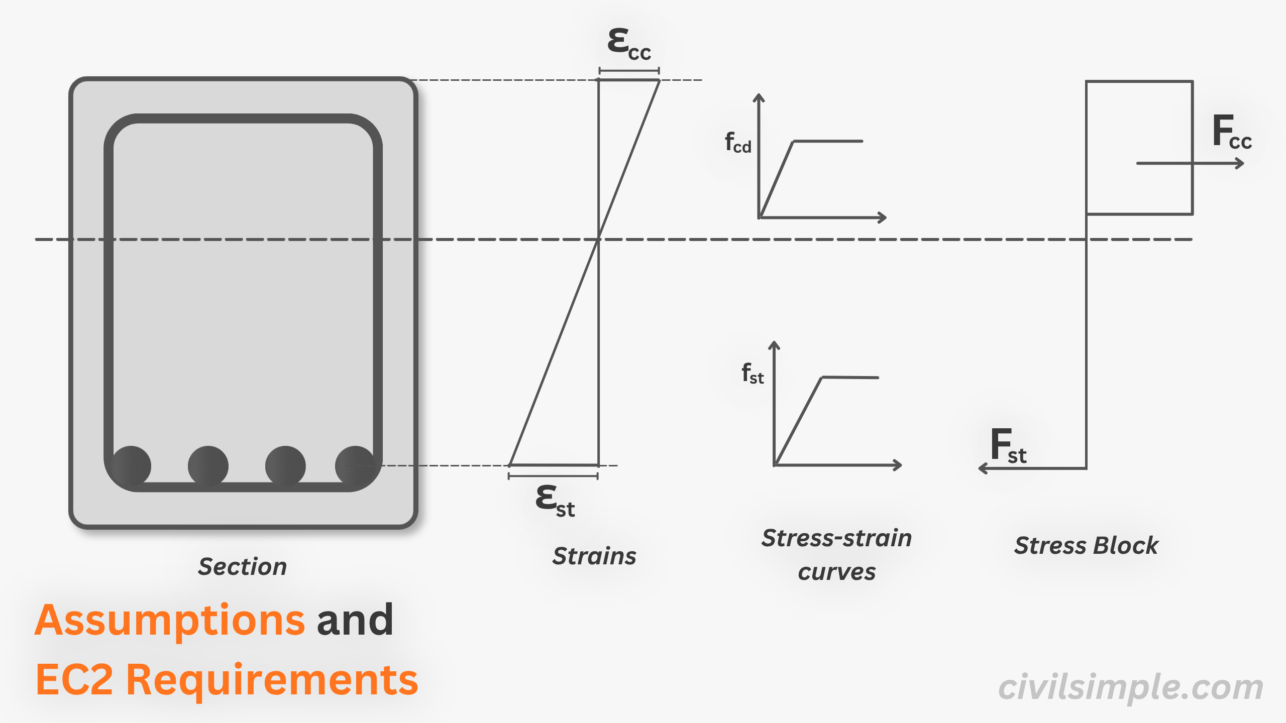
The RC design of members are depending on obersved and tested behaviours, though it can be complex, based on Cl.6.1 in BSEN1992-1-1, we should always remain these assumption taken:
1. Plane section remain plane Cl.6.1(2), BSEN1992-1-1
2. Stress in compression are derived by stress-strain curveCl.6.1(2), BSEN1992-1-1
3. Strain of rebar in tension or compression are same as surrounding concrete.Cl.6.1(2), BSEN1992-1-1
4. Tension strength of concrete is ignored.Cl.6.1(2), BSEN1992-1-1
5. Stress in reinforcement are derived by stress-strain curve.Cl.6.1(2), BSEN1992-1-1
6. Force equilibrium: Resutlant forces developed by the section must be in equilibrium.Section 6.4, BSEN1990
📜 Ductility and Code Requirements
While the assumptions above describe the mechanical behaviour of reinforced concrete sections, EC2 also imposes additional limits to ensure ductile and safe structural behaviour.
1. Tensile steel yields before concrete crushes, neutral axis xu/d is limited to 0.45, ensure sufficient ductility and rotation capacity Cl.5.5 (4), BSEN1992-1-1
2. To ensure minimum compression stripe, z/d ≤ 0.95 Good Common Practice
3. Maximum and Mimimum reinforcement ratio, 0.04Ac and 0.26 Cl. 9.2.1.1, BSEN1992-1-1
↔️ Upper and lower bounrdery of K, xu/d and z/d
Based on item 1. and 2. in ductility and code required, and the relationship between K, xu/d and z/d, we can conclude with below upper and lower limits.
Details derivative of these boundaries, please check out this article,Derivation of relationship of x/d, z/d and K.
📝Summary & Key Takeaways
- RC flexural design assumes strain compatibility and equilibrium, with bilinear material behaviour and no concrete tension.
- EC2 adds limits on neutral axis, lever arm, and reinforcement action to ensure ductile steel-yielding failure.
CivilSimple Team
The CivilSimple Team writes practical engineering guides for the profession and the curious. All articles are reviewed for technical accuracy before publication.