🔧 Shear Design Method - Truss Model
According to Section 6.2.3 of Eurocode2 (EC2, BSEN1992-1-1:2004), shear reinforcement design, truss model with compression strut with inclined angle θ and tension links ties with inclined angle α. Since vertical shear links is the most commonly used arrangement, this article focuses on the case where the shear links is vertical and only the inclination of the concrete compression strut, θ, is considered.
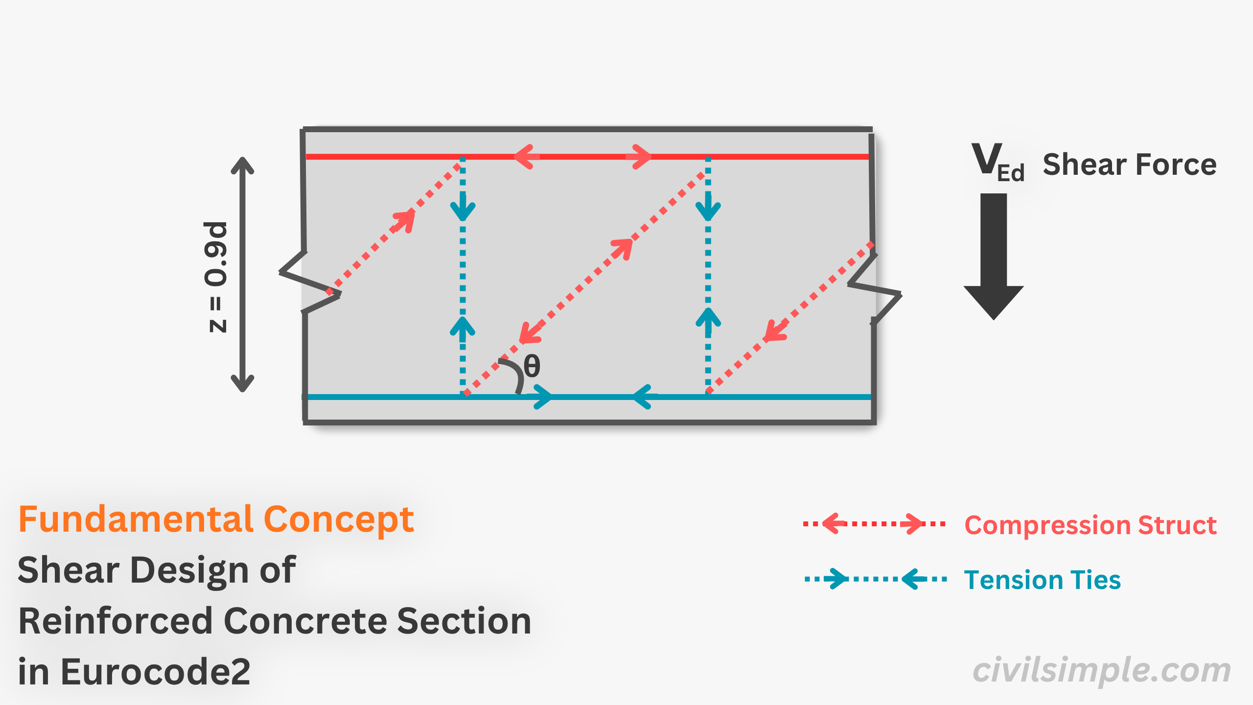
📐 Principle Behind Truss Model
In this principle, shear resistance is developed through the interaction of tensile vertical reinforcement, inclined compression struts, and the bottom tension chord. The shear capacity is then determined by satisfying force equilibrium First Principle Logic.
🔎 Derivation of Shear Resistance VRd,s
The shear resistance, VRd,s, is provided by the vertical shear links acting in tension. The derivation below illustrates how VRd,s is obtained from force equilibrium, in accordance with Eurocode 2. Eq 6.8,BSEN1992-1-1:2004
1. Horizontal length between tension ties = z • cotθ
2. Number of Asw provided in tension ties, n = z • cotθ / s
3. Total Shear Link Area provided in tension ties =n • Asw=(z • cotθ / s) • Asw
4. Material Strength of shear links = fywd
5. Shear Resistance (VRd,s)=Material Strength of Reinforcement • Shear Link Area=(fywd) • (z • cotθ / s • Asw)=(Asw/s)zfywdcotθ
🔎 Derivation of Maximum Shear Resistance , VRd,max
The maximum shear resistance, VRd,max, is governed by the capacity of the inclined concrete compression strut. The derivation below illustrates how VRd,max is obtained from force equilibrium, in accordance with Eurocode 2. Eq 6.9,BSEN1992-1-1:2004
1. Component of depth of compression strut = z • cosθ
2. Area of compression strut = bw • z • cosθ
3. Material strength of concrete = αcw • v1 • fck
4. Force of Compression strut, Fcc =Material strength • Area=αcw • v1 • fck • bw • z • cosθ
5. Max. Shear Resistance, VRd,max =Vertical Component of Force of Compression Strut=Fcc • sinθ=(αcw• v1• fck • bw • z • cosθ) • sinθ=αcwbwv1fcdz / (cotθ + tanθ) where cosθsinθ = 1 / (cotθ + tanθ)
🔢 Formula of Additional Longitindinal Force, ΔFtd
Last by not least, as mentioned above, the longitudinal reinforcement, acting as the bottom tension chord, needs to carry additional tensile force due to the applied shear force, VEd, as indicated below: Cl 6.2.3(7) & Eq 6.18,BSEN1992-1-1:2004
📝Summary & Key Takeaways
- Truss model is the principle taken by eurocode 2 for shear resistance analysis, where the applied shear force, VEd, is resisted by inclined compression struts, vertical shear links, and the longitudinal bottom tension chord.
- Shear resistance of a reinforced concrete section, VRd,s in Eurocode 2, is the design shear capacity provided by shear links, with equation Eq. 6.8, BSEN 1992-1-1:2004.
- Maximum shear resistanceVRd,max is govern by capacity of the inclined concrete compression strut, with equation Eq. 6.9, BSEN 1992-1-1:2004.
- Additional longitindinal force which carried by the bottom tension longitindinal reinforcement is Eq. 6.18, BSEN 1992-1-1:2004.
CivilSimple Team
The CivilSimple Team writes practical engineering guides for the profession and the curious. All articles are reviewed for technical accuracy before publication.