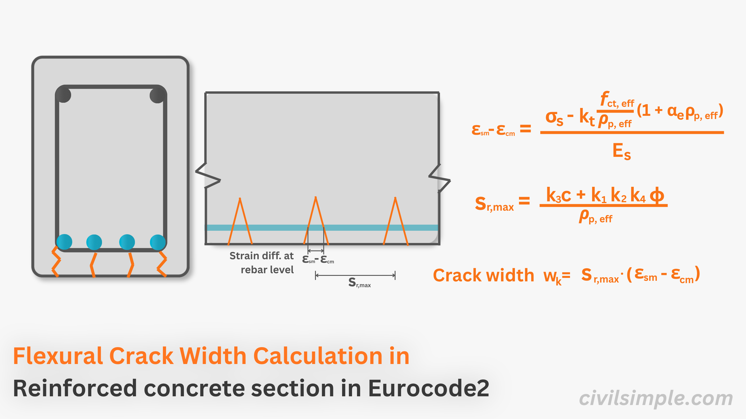
❓ What is Crack Width?
Cracking in reinforced concrete section occurs when the tensile stress induced by bending, shear, torsion, or restrained shrinkage exceeds the tensile strength of the concrete.
Because concrete is weak in tension, reinforcement is provided to carry these tensile forces. However, for the reinforcement to take up the tensile stress, the surrounding concrete must stretch and eventually crack. To protect reinforcement from corrosion and ensure structural integrity and appearance, crack widths must be limited to acceptable values depending on the environmental exposure class.
Crack width control is the design process of ensuring that any cracks that form are kept within acceptable limits (often 0.3 mm or 0.4 mm) under quasi-permanent load combinations.
Common symbol in eurocode:
wkThe general formula for crack width is:
❓ What crack analysis is considering?
To understand what exactly happening inside the crack analysis, let's briefly understand the major components: 1. mean strain different at tension reinforcement level and 2. maximum crack spacing.
1. Mean Strain different at tension reinforcement level, εsm - εcm
When a load is applied, tensile stress is induced in the tension zone of the section. The steel reinforcement carries most of the tensile stress and therefore undergoes strain. Although the surrounding concrete also experiences tensile stress, its strain and elongation differ from those of the reinforcement. This difference in deformation leads to the formation of cracks
The graph below illustrates the difference in strain at the level of the tension reinforcement.
In calculation of the strain, the strain is obtained by dividing the stress by Young's modulus: .
Therefore, the strain difference can be calculated using the formula below, as recommended in Eurocode 2. The equation is based on first principles, with empirical coefficients introduced to account for the actual behaviour of reinforced concrete.
2. Maximum Crack Spacing, sr,max
The maximum crack spacing depends on the geometry of the reinforcement within the section, as suggested in below diagram:
- For rebars spacing within section < (within 5(c + ϕ/2)): he maximum crack spacing is calculated using an empirical equation based on the concrete cover, bar diameter (ϕ), and the effective reinforcement ratio.
- For rebars spacing within section > (within 5(c + ϕ/2)):, the crack spacing is assumed to depend primarily on the geometry of the concrete section.
🧩 Dependence of Crack Width from Section Properties
From the above consideration an eurocode 2, we can conculded that the crack width is depending on .. From Eurocode 2, wk mainly depends on: Cl. 7.3.4, BSEN 1992-1-1:2004
- Concrete cover, c
- Bar diameter, ϕ
- Effective tension area of concrete, Ac,eff
- Steel stress under quasi-permanent load, σs
- Effective reinforcement ratio, ρp,eff =
If you want to reduce the crack width, can consider:
reduce the stress (moment at the section)
incrase the section depth and breath
reduce concrete cover
increase the size of steel rebar and also the area
🔍 Formula of Crack Width wk
The characteristic crack width can be calculated using the below formulas Eq. 7.8, 7.9, 7.11 & 7.14, BSEN 1992-1-1:2004.
fct,eff = mean value of tensile strength of the concrete effective
σs = stress in tension reinforcement assuming a cracked section
αe = Es / Ecm
kt = a factor dependent on the duration of load
ϕ = bar diameter
k1 = coeff. which takes account of bond properties of the bonded reinforcement [0.8 for high bond bar, 1.6 for bars with effectively plain surface]
k2= coeff. take account of the distribution of strain [0.5 for bending, 1.0 for pure tension]
k3 = 3.4
k4 = 0.425
c = cover to longitudinal reinforcement
ρp,eff= ( As + ξ₁ A'p)/ Ac,eff
📍 Quick Guideline for Common Crack Width related calculations
Given a section with an applied quasi-permanent moment MEd, find the crack width wk
Calculate Steel Stress (Cracked Section)
x = depth to neutral axis of the cracked section
Icr = cracked second moment of area
σs = (MEd / Icr) ⋅ (d - x) ⋅ αe
Determine Effective Tension Area
Calculate effective height: hc,ef= min(2.5(h-d), (h-x)/3, h/2)
Calculate area: Ac,eff = hc,ef ⋅ b
Calculate effective ratio: ρp,eff = As / Ac,eff
Calculate Strain Difference
εsm - εcm = [σs - kt(fct,eff / ρp,eff)(1 + αe ⋅ ρp,eff)] / Es
Check minimum limit: must be ≥ 0.6(σs / Es)
Calculate Maximum Crack Spacing
Determine bond factors: k1 = 0.8, k2 = 0.5
Apply EC2 constants: k3 = 3.4, k4 = 0.425
sr,max = 3.4c + 0.8 ⋅ 0.5 ⋅ 0.425 ⋅ (ϕ / ρp,eff)
Determine Final Crack Width
wk = sr,max ⋅ (εsm - εcm)
Ensure wk ≤ wmax (e.g., 0.3mm)
📝Summary & Key Takeaways
- Concrete cracking in tension is an expected part of reinforced concrete behavior. Crack control ensures these cracks remain small enough to protect the reinforcement from corrosion and maintain appearance.
- The width of a crack is primarily determined by the maximum crack spacing and the difference in strain between the elongating steel and the surrounding concrete.
- Common crack width calculation procedures are demonstrated in this article, guiding you through determining the effective tension area, calculating steel stress, and establishing the final characteristic crack width step-by-step.

CivilSimple Team
The CivilSimple Team writes practical engineering guides for the profession and the curious. All articles are reviewed for technical accuracy before publication.